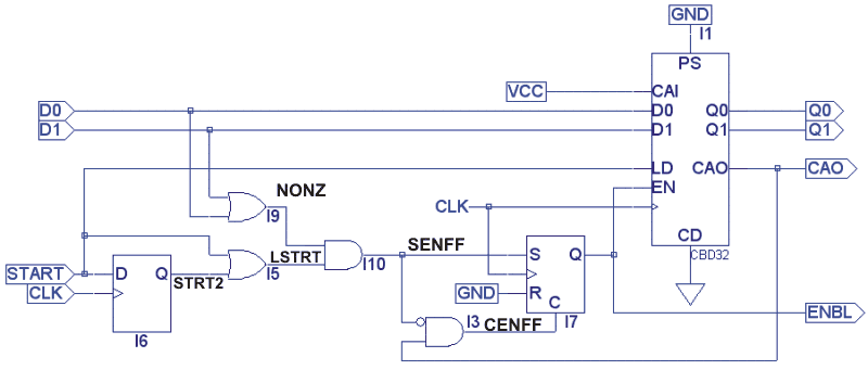
| CAO |
Cascade out. Goes
high when the counter has reached zero. (If the counter's EN
input is low, CAO will not be high, even if the counter contains zero. |
| CLK |
Clock |
| CENFF |
Clear enable flip-flop. |
| D0 & D1 |
Data inputs. The
binary number on these inputs determines how many clock pulses the
counter will count until reaching zero. (The counter is a down counter.) |
| ENBL |
Enable. Used both for
the down counter in this circuit as well as any circuitry that needs a
pulse that's a certain number of clock pulses wide. (The octave shifter
is one such circuit.) |
| LSTRT |
Long start signal.
The start signal put into this circuit should be only one clock period
wide. The D flip-flop in this circuit gives a start signal that's one
clock pulse delayed. Thus, the LSTRT output of the OR gate will be high
for two clock pulses. |
| NONZ |
Non-zero input data. If the input data is zero, the counter shouldn't do any counting. |
Q0 & Q1
|
Down-counter outputs. |
| SENFF |
Set enable flip-flop |
| START |
Start pulse. This
pulse should be only one clock-period wide. Once the above circuit
receives this start pulse, the down counter will count down and
continue until it reaches zero. |