- Create a new folder
(gj05_09) on your flash drive (or
wherever) for this project.
- In Windows Explorer,
copy the following files into the
gj05_09 folder:
- The schematic file
from the gi21_13 Tone Translator Up
Counter project.
- The schematic file
from the gj01_10 Improved Timing
Circuit project.
- Open Lever, and start
a new project whose files will be
kept in the gj05_09 folder.
- Use gj05_09 as the
file name.
- With the device number
(LC4256ZC-45T100C) highlighted, Use Source,
Import
to import the gi21_13
and gj01_10 schematics.
- Highlight the gi21_13
schematic, and in the other window
double-click Generate Schematic Symbol.
- Do the same for the
gj10_10 schematic.
- Double-click gi21_13
(in the Sources
in Project Window) to open
it into the schematic editor.
- If the CD
input at the bottom of the CBU14 counter
doesn't have an input pin titled LDOUTCNT, create this input pin and
connect it to CD.
- Click File, Matching
Symbol and then save the
schematic.
- Click Window, Library
Manager.
- In the Library Manager
window, click File, Open Folder
and choose the
gj05_09 folder.
- Open the schematic
editor.
- In the Drawing Toolbar,
click the Add
Symbol icon.
- In the top list box,
if Local
isn't already highlighted, highlight it.
- In the bottom list
box, click the gi21_13 symbol and place
it in the schematic's work area.
- Do the same for the
gj10_10 symbol.
- Increase the size of
the drawing area by clicking File,
Sheets, Resize, D
-34.00" 22.00"
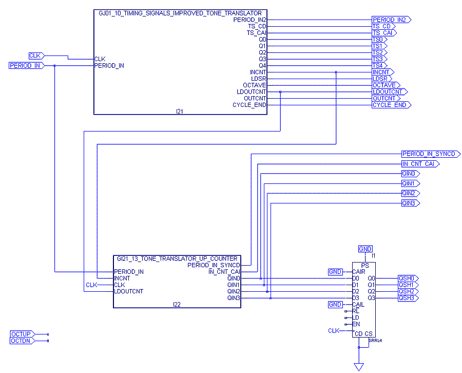
- Connect up the circuit
as shown in the schematic below.
- The SRRL4 macro is a
right/left shift register. For
information on how
it works, go to the Reference
Material for Lever Macros page
to find out how to use the Macro
Library
Reference Manual (part of the
Lever help utility that resides on your hard drive). Your job is
to add a couple of gates and connect some wires to provide inputs
to shift register pins RL, LD, and EN so that the
entire
circuit
will produce the waveforms shown at the bottom of this Web
page.
- Hint, you'll need
to use the OCTUP and OCTDN input pins as inputs to some of these gates.
- When OCTAVE is high,
and either OCTUP or OCTDN is high,
the shift register should shift in the appropriate direction.
- If OCTUP is high,
the
shift register should shift in a direction that will produce a tone
translator output frequency that is twice as high as the input
frequency from the microphone.
- Likewise, OCTDN
should make the frequency half as high as
the input frequency.
- Right
click here to get the test
vector file, and
then choose Save
As.
|